This is just a blog of how I made the AllStar node into a desktop radio with a pleasing look. The actual software build of the Node isn’t covered here since the date the radioless node was built, new versions of AllStar node software have been released. Freddie Mac the Ham Radio Crusader has many excellent tutorials on how to get up a node up and running. https://www.youtube.com/@HamRadioCrusader
The story of why I wanted to build it like this. I have seen many tempting videos and web articles by some very experienced constructors and thought I could do similar with my own variation. I have already built 2 AllStar nodes with radios for myself and a good radio amateur friend. The last build was modified after the 5v buck converter became noisy and my audio suffered the inevitable squeal noise in the background. This is my own fault for choosing a cheap buck converter and poor wiring and separation practices. I was learning and because of the day job, I don’t get much time to spend developing.
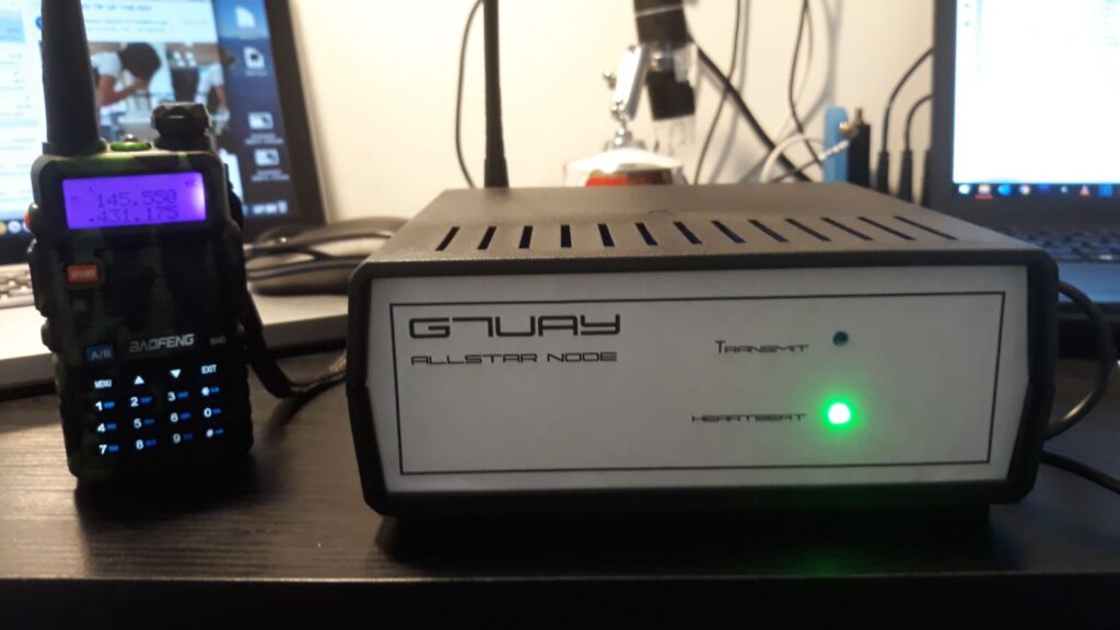
This was AllStar node number 1, which I reconfigured and gave to a radio amateur friend.
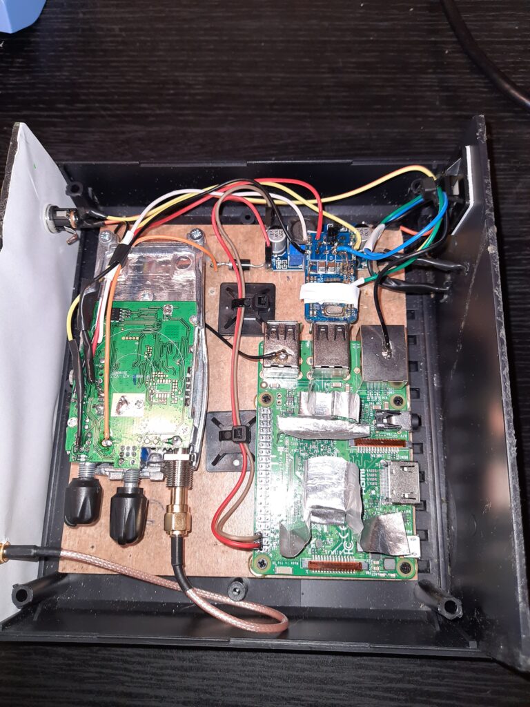
The insides were not pretty. You can see the buck converter at the top, too close to the USB Audio dongle.

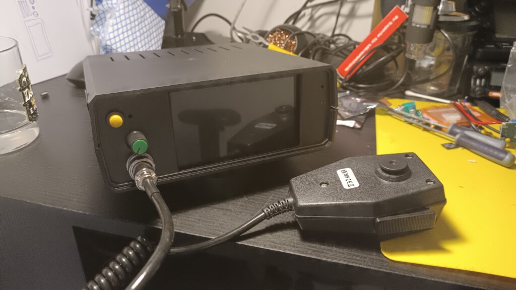
AllStar node number 2 which I modified a while ago by removing the internal Boafeng donor radio and replacing it with an externally-mounted mobile radio which also serves as a general VHF/UHF dual band set or Packet radio just be swapping the microphone and speaker connections.
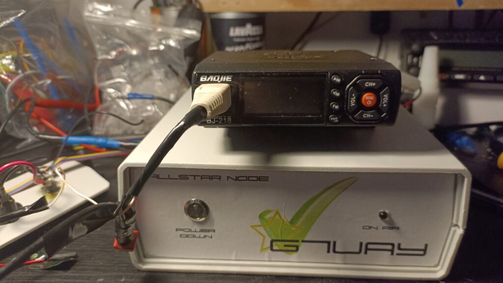
The modified AllStar node with radio.
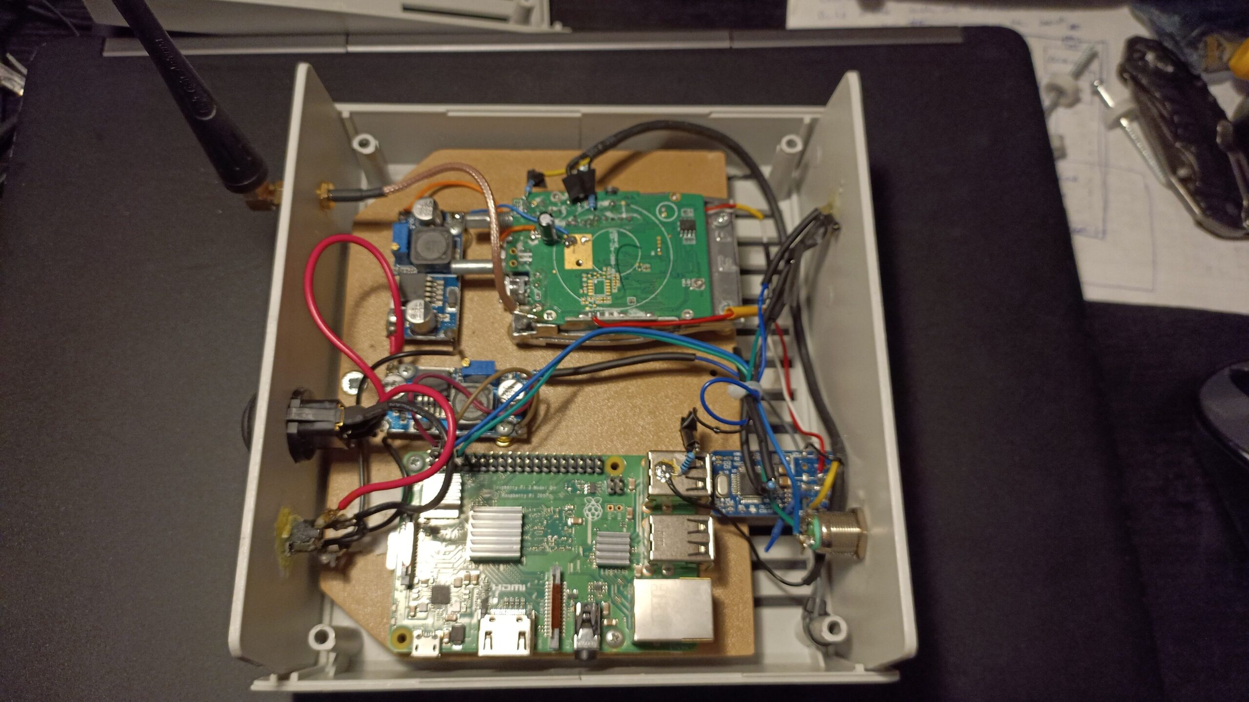
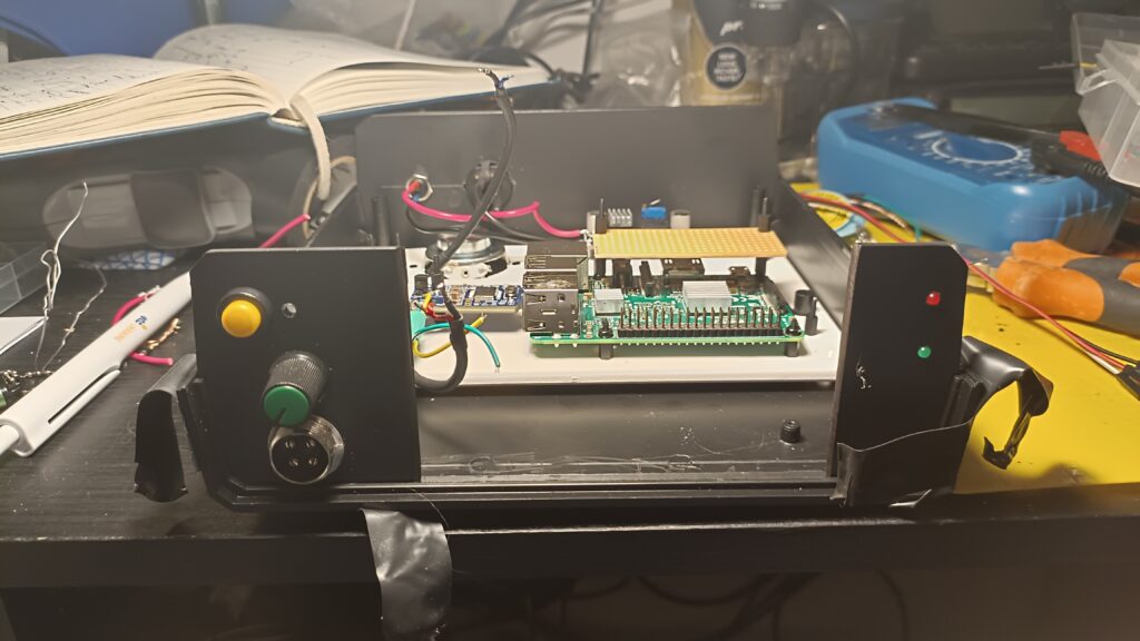
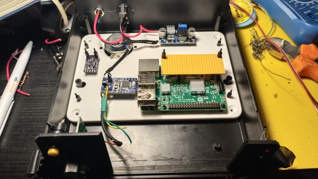
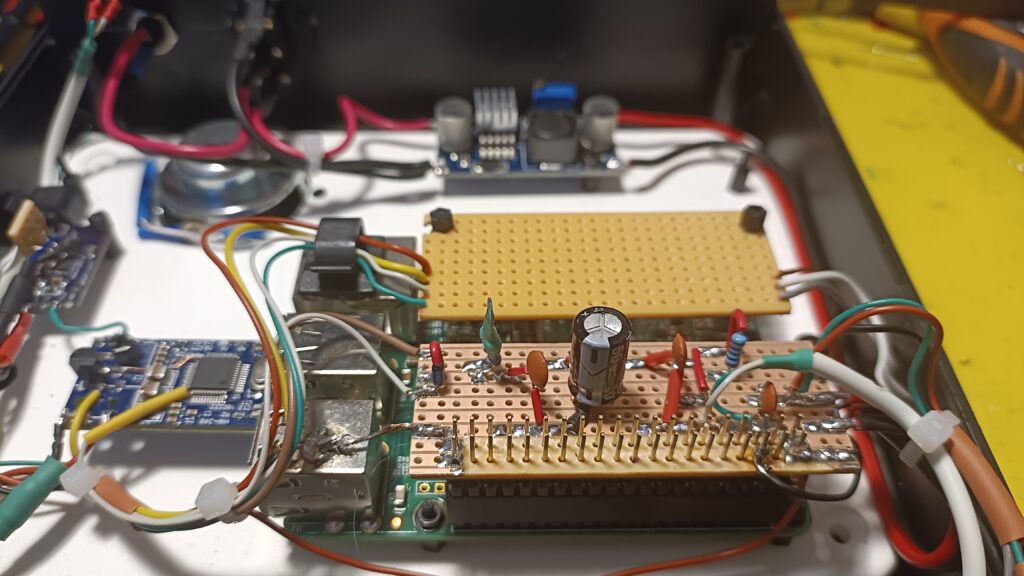
This is a little neater. I used 2 buck converters one to drive the radio with 7 volts and the other for the Raspberry Pi at 5 volts. No background squeals on this one.
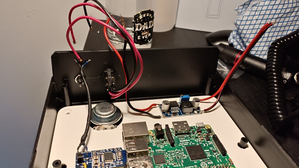
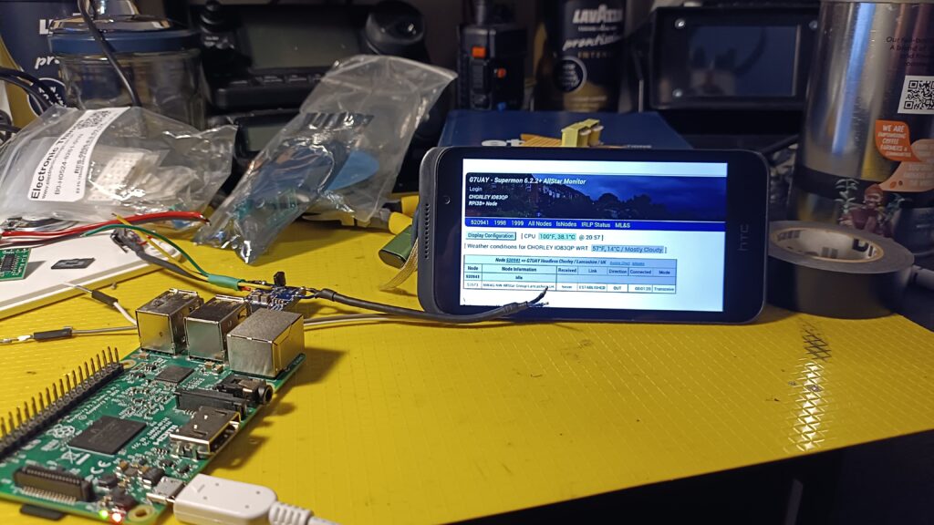
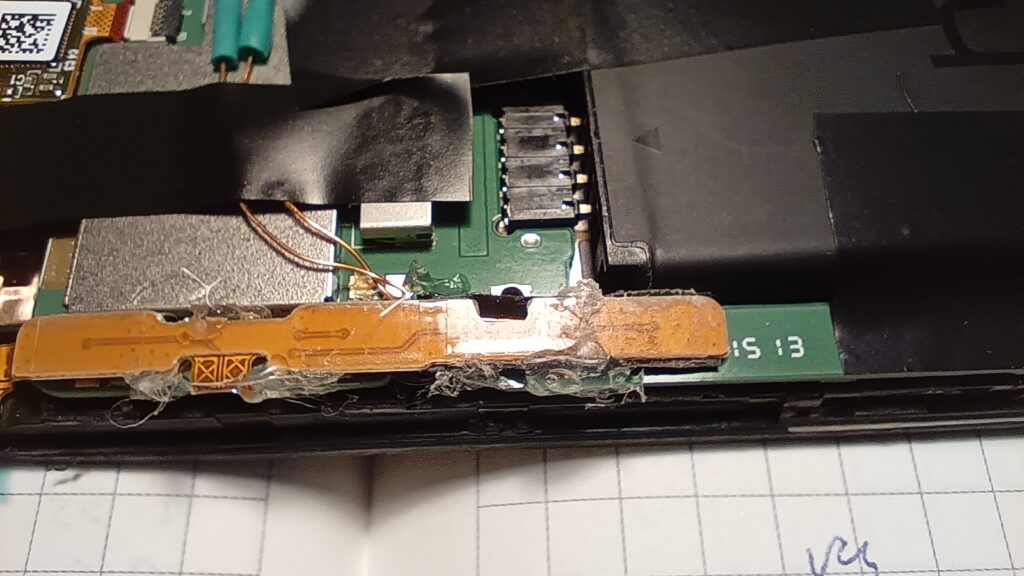
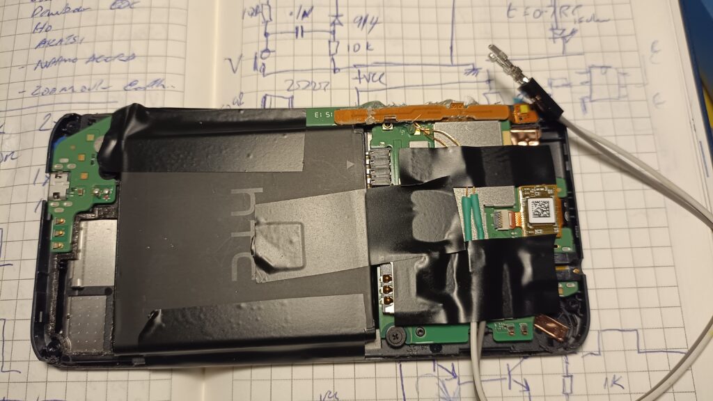
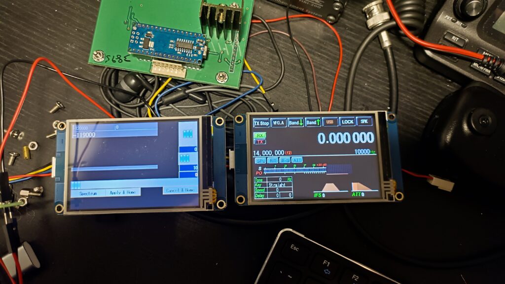
The modified phone completed and tested ready for installation.
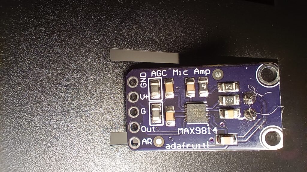
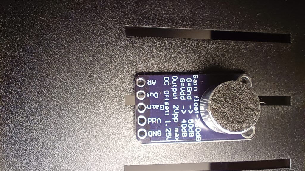
During testing, I found the transmit audio from the off-the-shelf cheap CB radio microphone was low. I modified this inexpensive microphone amplifier board which had manually selectable gain. But it was either too much or not enough. I added alternative resistors to get a compromise of around 15dB gain which works a treat. You can change the transmit audio level from within the AllStar setup but I prefer to get the audio level right in hardware first then this can be adjusted in software later.
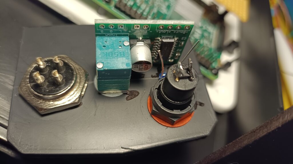
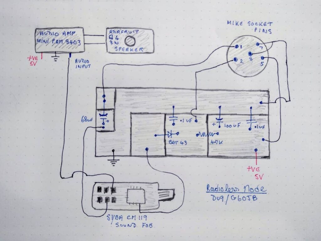
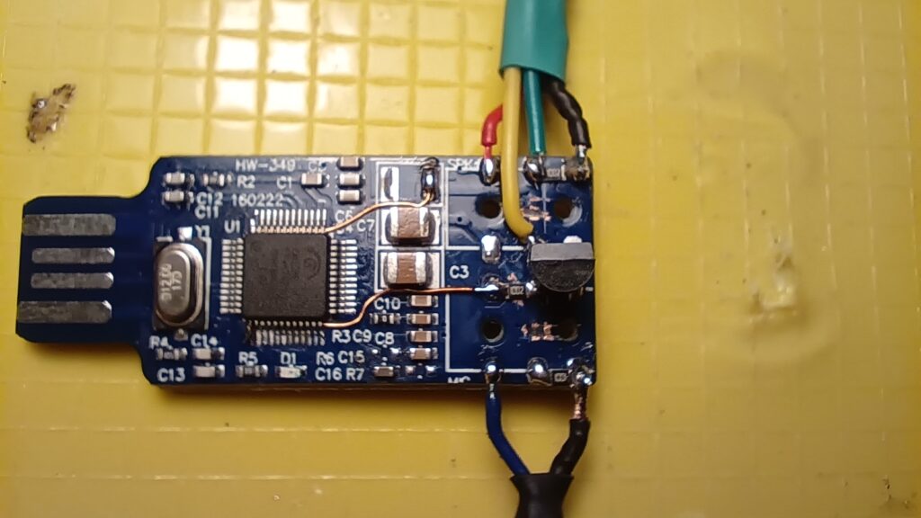
Credit to G6OJB saving me the time of doing my own design. This one works very well and I throughly recommend the BAT43 diode to protect the GPIO from any potential voltage getting into the GPIO and destroying the CM108 chip. The design above used the newer CM119 which is similar to the CM108 which was in short supply.
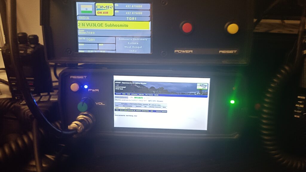
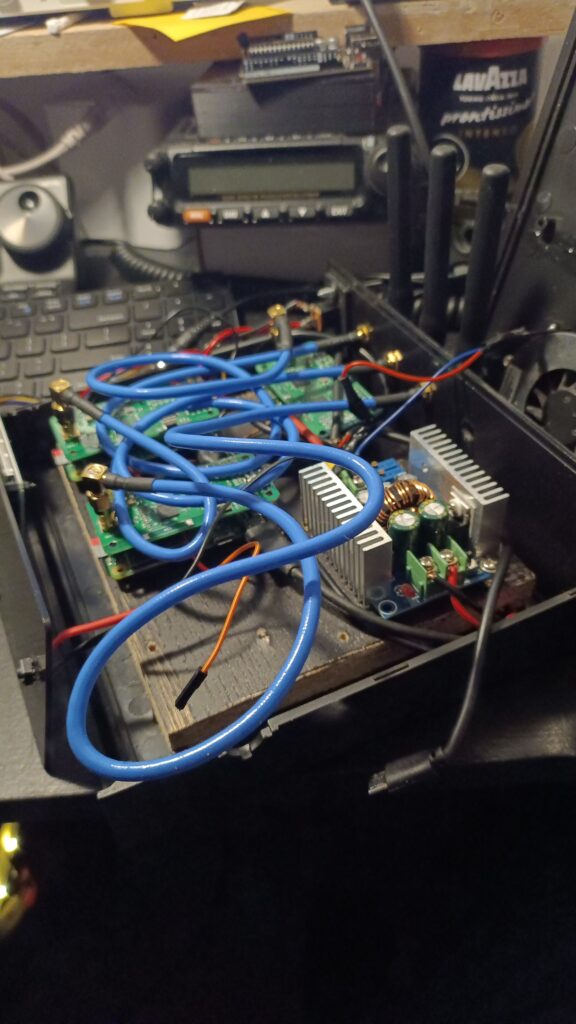
This was when I was trying to fit MMDVM number 4 in an already messy, untidy case. It has DMR, C4FM/Fusion, D-Star and now POCSAG MMDVMs installed. Its a bit of a gimmick really since I wanted to have 4 modes all on independently at the same time. I was going to use an Arduino microcontroller plus some detecting and switching to manually or automatically select the MMDVM information to display on the 3.5″ Nextion touch screen. This project generated a lot of heat so I had to install a slim fan I recovered from a scrap laptop to help with ventilation. It worked surprisingly well. 3 Hotspots were on UHF 70cm band and the other on VHF. Even on the minimum power output of milliwatts, one MMDVM would de-sense the others and struggle to “hear” my radio on low power if I was more than 5 metres from the desk.
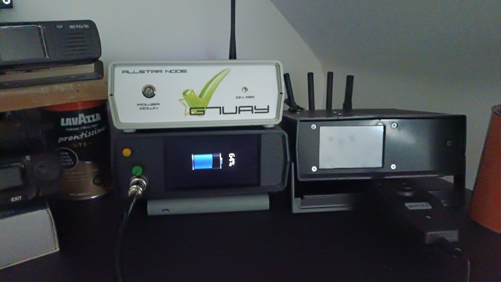
Family picture with the Radioless AllStar node battery charging in portrait mode on its side.